USB Type-C is Coming
USB Type-C is Coming: 3 Things You’ve Just Gotta Know
With its “insert either way” simplicity and legacy channel transport, Type-C is the last connector a user will ever need. But the burden’s now on the designer to understand Type-C.
Say, have you heard about Apple’s choice of a single Type-C USB 3.1 port on the new Macbook? It replaces all the other ports except the headphone jack. As shown in Figure 1, Type-C can be used for:
- USB 1.1/2.0/3.0/3.1
- HDMI
- Ethernet
- DisplayPort
- Power
- Audio
- Lots more multi-gigabit channels.
USB 3.1 (Type-C) runs up to 10 Gbps, supports 100W for charging, and as a bonus, can be inserted either way like Apple’s own Lightning connector on an iPhone/iPad. According to the USB-IF trade group, it’s a “20 year connector,” and it looks like a real winner. And therein lies the challenges for designers: dealing with signal integrity and speed issues in your embedded design; accommodating 100W of power that can flow in either direction!; and interfacing Type-C to the legacy interfaces listed above.
Whew! You need some Quick Tips. Here goes.
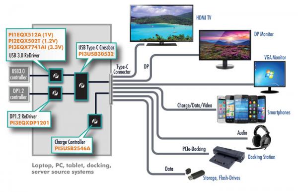
Figure 1: The Type-C Connection is designed to replace all of these...and more
Quick Tip #1: To Re-Drive (or not) Your Type-C
Spec’d to operate at up to 10 Gbps, USB 3.1’s Type-C connector can move all kinds of data over just 24 signal lines (Figure 2). There are 12 lines per side on the dual-directional connector (A side and B side), and only four of them map to USB 1.1 and 2.0 (Vcc, Ground, D , D-); the rest of them are for differential signals or power.
As if the capabilities of USB Type-C shown in Figure 1 weren’t impressive enough, these 12 lines can do many things at once. For instance, the Type-C cable can carry up to four DisplayPort lanes simultaneously, or USB 3.1 with two DisplayPort lanes, plus USB 2.0 and USB-PD (Power Delivery). Alternatively, HDMI, PCI Express and other differential standards can also be mixed in. The cable supports 5 Gbps at 2m or 10 Gbps at 1m.
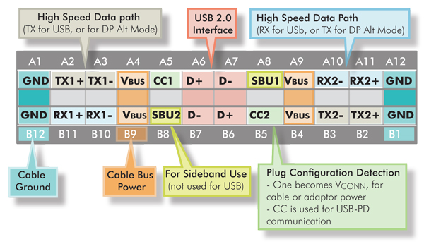
Figure 2: USB Type-C pins and Signal Lines
(Courtesy: http://www.vesa.org/. the folks who support the DisplayPort specification)
The take-away for designers is that there’s a lot going on over the cable, plus a lot of high-speed signaling occurring within the Source and Destination embedded systems on either side of the cable. Those 10 Gbps lines represent channels that pass from/through IC pins, PCB traces, PCB vias, flex cables or flex circuits, connectors and the Type-C cable itself.

Figure 3: USB3.1 Gen 1 Loss bugdet for various USB legal configurations.
(Source: USB3.1 Channel Loss Budget. Rev 1.0 March 1 2015 in USB.org website
http://www.usb.org/developers/docs/whitepapers/USB_3.1_Loss_Budget_Rev_1.0_-_2015-03-02.pdf
Figure 3 represents the channel loss allocation from one end (host or dual role) to the other end (device or dual role). In the case of type C to type C, since it is dual role port, the loss at either end is same at 6.5dB and the loss allocation for 2meter cable assembly is 7dB for total channel loss of 20dB. Since type C is reversible, there will be mux at the type C connector. So, PCB trace plus mux insertion loss must be contained within 6.5dB. Eg. Assume USB host connecting 3” of PCB trace to mux with 1db Loss and additional 3” to type C connector. Total loss assuming inner trace is 3×0.8 1 3×0.8=5.8dB. Hence it is within the loss budget and hence don’t need a USB3 redriver. If the distance exceeds that, a redriver is required before the type C connector.

Figure 4: Long USB 3.0 traces on a dense ultra-mobility device PCB need redrivers to clean up signals and recover signal integrity problems. In portable platforms, external cables and flex circuits compound the SI problems.
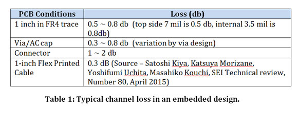
In signal integrity (SI) terms: an open eye at the Source will most likely be a closed eye at the Destination as data and the encoded signal clock traverse this long and interrupted channel. Some typical losses are shown in Table 1.
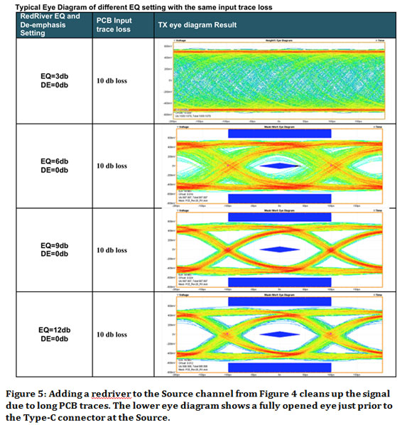
The Quick Tip solution? Use a redriver, a tiny active signal amplifier that almost miraculously fixes signal integrity problems by opening the SI eye. Inserted into the channel right before the Source Type-C connector shown in Figure 4 (lower right), the eye will be opened by the redriver located close to the connector and signals successfully sent over the Type-C cable.
Figure 5 shows various eye diagrams of the USB 3.0 channel using a 5.0 Gbits/s Pericom PI3EQX7741AI redriver with equalization and signal emphasis. The key picture is the bottom one, showing how the redriver opens the eye and compensates for all the SI boundaries between the source IC and the Type-C connector. All of this, by the way, is still within the Source device (at the Tx end).
Quick Tip #2: Power(ful) Options
The new Type-C connector can handle up to 100W for powering monitors or for charging devices as large as laptops, notebooks or 2:1’s (Figure 6). Additionally, power can flow in either direction, so your smartphone could conceivably recharge your laptop (for a short time). Previous USB charging schemes were covered under the USB-IF BC 1.2 (battery charging) specification (refer to this article “How USB Charges Just About Any Electronic Device”). Type-C’s new specs are covered in the Power Delivery 2.0 (PD) specification (refer to “Top 3 Essential Technologies for Ultra-mobile, Portable Embedded Systems”).

Figure 6: The USB Power Delivery (PD) specification allowsup to 100W over Type-C to power myriad devices directly.
(Courtesy: USB-IF; www.usb.org)
The mechanism for determining power requirements, selecting voltages, and supplying current per the PD spec are complex and based upon USB-IF protocols (the reader is encouraged to check out the aforementioned articles). Table 2 lists the key power options in Type-C per the PD spec.

Table 2: USB Type-C Power Options. The Power Delivery (PD) spec covers the whole range and includes earlier USB2.0, 3.0 and BC 1.2 power specifications. Of note: 100W and bi-directional power in Type-C
Of note is how the new 100W (either direction) PD options are intended to co-exist with the legacy BC 1.2 specifications. Designers need to be aware of what power requirements their system is meant to provide and incorporate the necessary charging, switching and enumeration circuitry. For all but the latest PD specification, the maximum USB power is 15W (5V @ 3.0A), which is sufficient for all handheld mobile devices, portable HDDs and USB accessories. Only laptops and monitors (arguably not “embedded systems”) are likely to need >50W (Figure 7).

Figure 7: Most handheld and embedded systems will require 15W or less per the USB-IF's BC 1.2 specification
Quick Tip #2 is that Type-C provides myriad ways to power and charge devices—at either end of the cable. Designers need to carefully read the USB-IF specifications referenced above and be careful not to over-design your embedded system. That is: 100W charging isn’t needed for any of the embedded or ultra-mobile devices on the right-hand side of Figure 8.
A fully configured USB 3.0 Type-C system supporting DisplayPort, legacy USB 2.0 as well as GPIO and I2C serial is shown in Figure 8. Not just presented here for discussion purposes, this is a real system that shows the capability of the Type-C connector even if not used with USB 3.1. In fact, because of Type-C’s capabilities—including Power Delivery—many designs may stay with USB 3.0 while incorporating alternate channels as shown.
Of note in Figure 8 are the Type-C PD controller (controlled by I2C or GPIO), the crossbar switch allowing up/down connector insertion, and the enumeration block for charger detection (two devices shown: host and device sides). For designs needing less than the 100W maximum, say, 15W, a PD controller isn’t required.
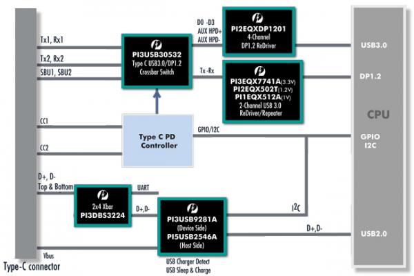
Figure 8: A fully configured, Type-C equipped USB 3.0 system that also includes USB 2.0, DisplayPort (DP) 1.2, and I2C/GPIO.
(Courtesy: Pericom Semiconductor.)
Quick Tip #3: It’s Hard to Leave a Legacy
Referring back to Figure 1, it’s clear the Type-C connector and cable should be able to replace most legacy serial interfaces, from PCIe to HDMI. It will even replace all previous versions of USB connectors and power adapters.
But it will take time to transition to an all-Type-C world; in the meantime, embedded designers will need to convert from one signal type into another. For example, in-system PCI Express will need to be converted to run over Type-C and possibly alongside USB 3.0 or 3.1. DisplayPort, HDMI, SATA and others will similarly need to be converted. Most of these transitions will happen in-system at the Source and Destination.
A block diagram showing how multiple standards and connector types come together in one system is shown in Figure 9. The figure shows an example of a digital monitor where conversion from Type-C to Display port and USB 3.0 occurs using Pericom devices: PI3USB30532 to separate DP and USB3.0, PI3EQX7742AI to provide USB3.0 redriving, PI3WVR12412/PI3VDP12412 to provide DP muxing, PI3DBS3224 to provide the USB 2.0 crossbar function and PI3PCIE3242 to provide USB 3.0 crossbar function to USB 3.0 hub.
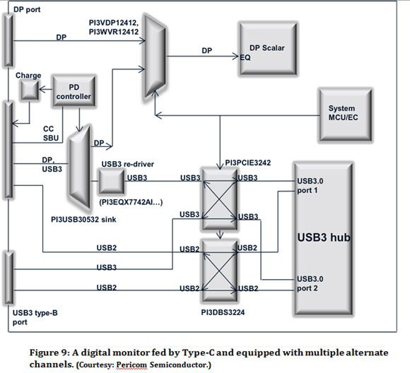
This is a digital monitor fed by Type-C. But the monitor also provides multiple output options including: USB 2.0 and 3.0 (type B) and DisplayPort 1.2—likely for a second display in a dual-monitor configuration.
Besides in-system signal conversion, consumers may find it useful to have active cables that do the conversion for them. This is attractive when a new Type-C system needs to interface with a legacy system. Some cable manufacturers are already working on cable adapters that have Type-C at one end and the legacy standard on the other.
The cable will include embedded circuitry that does the conversion within the cable itself. And why not? USB 3.1 Type-C can supply power and channel wires, and redrivers can also be included at either end (or both ends) to deal with any signal integrity issues.
The Quick Tip takeaway here? Despite USB 3.1 and Type-C’s additional speed and features, there will be a period of time when support to existing interfaces will be needed thru dongle, docking or cable converters.

 Email
Email Asking price